Comparators#
A comparator is a device that takes two inputs, one called \(V_{in}\), and one called the threshold, \(V_{TH}\). If \(V_{in}\) is greater than \(V_{TH}\), the comparator returns a high signal, otherwise its output is low.
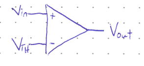
Essentially, the comparator asks “Is \(V_{in} > V_{TH}\)?”
If \(V_{in} > V_{TH}\), \(V_{out}\) = High.
If \(V_{in} < V_{TH}\), \(V_{out}\) = Low.
Note that the case where \(V_{in}\) is exactly equal to \(V_{TH}\) should also return a low signal, but this situation rarely arises in the real world because all of the input signals will have some noise component.
The orientation of a comparator can also be reversed, so that the question becomes: Is \(V_{in} < V_{TH}\)?
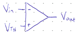
Although the symbols look similar, do not confuse a comparator with a NOT gate. Also, no current flows through an ideal comparator.
Aside: How does a comparator work?
It is derived from an analog electronics component called an “Operational Amplifier” or more simply an Op-Amp. An Op-Amp uses transistors and feedback to amplify a small difference between two input currents. The ideal output of a differential amplifier is \(V_{out} = A(V_{in}^{+} - V_{in}^{-})\) where \(A\) is a constant gain factor. However, the amount of amplification is limited by two supply rails (\(V_{S+}\) and \(V_{S-}\)) that supply power to the circuit. To make a comparator, we simply crank up the gain so that any small difference is saturated to the supply limit, and ensure that \(V_{S+}\) is equal to our high voltage level and \(V_{S-}\) our low level (e.g. \(V_{S+} = 5\,\text{V}\) and \(V_{S-} = 0\,\text{V}\)). In this manner, there is no longer amplification, but a bimodal High or Low output.
Setting the Threshold Voltage#
In order to set the threshold level we can use a voltage divider. \(V_{TH}\) is often expressed as some fraction of \(V_{cc}\). (Recall that \(V_{cc}\) stands for common collector and is equal to our high signal level, typically 5 V.)
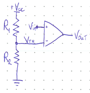
From KVL:
and
Rearranging and substituting (2) into (1) gives:
Concept Check Orange Box with Circle Exclamation icon
Concept Check:
What will the threshold voltage of the comparator above be if \(R_1 = R_2\)?
Green Solution with light bulb icon
Solution
If \(R_1 = R_2\), then the threshold level is exactly \(\frac{1}{2}V_{cc}\).
Comparator Output and The Problem with Noise#
Let’s examine what happens as we raise the input voltage from 0 to \(V_{cc}\) and then lower it again for the specific case where \(R_1 = R_2\).
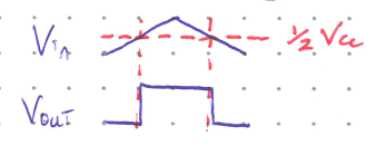
We can see that the comparator gives us a clear digital signal even though the the voltage level varies continuously. We get a nice, clear transition from a low output to high, and back again. However, we’ve assumed that the input voltage rises and lowers perfectly smoothly. In a more realistic scenario, the inherent noise in any input signal can lead to very undesireable behaviour.
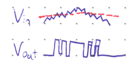
The noise causes very rapid flickers between the on and off states as it makes the input quickly vacillate above and below the threshold. This behaviour could very easily lead to circuits not functioning correctly. How can we design a circuit that can correct this noisy behaviour?
Schmitt Triggers#
To deal with noisy signals (which all real-world signals are) we use what is known as a Schmitt Trigger. The comparator is combined with feedback to create two different trigger levels depending on the current output state. This concept is known as a hysteresis loop: To go high has one trigger level, but once that high threshold is reached it switches to a different lower threshold to go low once again. As long as the two thresholds are far enough apart, noise should not cause undesired transitions, as shown in the timing diagram below.
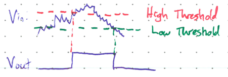
The hysteresis loop can be represented on a graph like so:
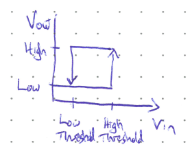
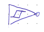
Any logic gate that uses a Schmitt Trigger at its input is symbolized using this loop. For example: a Schmitt NOT Gate aka a Schmitt Inverter.
Schmitt Inverter Construction#
A Schmitt Inverter is made using a comparator and feedback.
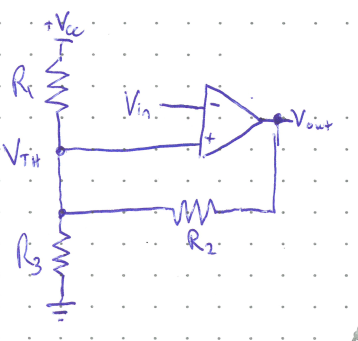
So how does this work? Let’s start by assuming \(V_{in} < V_{TH}\).
This means that \(V_{out} = \text{High} = V_{cc}\).
What is the threshold level that we would need to reach to change the output to low?
First, we note that since \(V_{out}\) is High, current will flow from the output, through \(R_2\) and then to ground. From KCL then we have:
where the subscript denotes current flowing through the corresponding resistor.
From KVL we have:
Rearranging (2) gives:
and doing the same for (3) yields:
From Ohm’s Law,
This is the high threshold level. For the case where \(R_1 = R_2 = R_3\), then \(V_{TH} = \frac{2}{3}V_{cc}\).
Once \(V_{in}\) is raised past that high threshold level, the output of the comparator switches to low. What does our new threshold level become when \(V_{out} = 0\)???
Since \(V_{out}\) is now 0 V, current will flow the other way through \(R_2\), and so our KCL equation becomes:
Ohm’s Law gives
And KVL gives
This is our new low threshold level. If \(R_1 = R_2 = R_3\), this is \(\frac{1}{3}V_{cc}\).
Therefore, the inverter won’t change from low to high until the input voltage falls below the new threshold.