Capacitors#
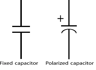
On a circuit diagram, a capacitor is symbolized by two straight parallel lines, or sometimes with one of the lines curved to show that the capacitor is polarized.
The simplest capacitor is two parallel metal plates separated by a small gap filled with air. We can use a DC voltage source to pump electrons from one of the plates and deposit them on the other, creating a charge imbalance. If the connections to the voltage source were removed, the electrons on the capacitor plates would have nowhere to go, and the charge imbalance remains (storing energy in an electric field between the plates). The capacitor could then be used to power other circuits by connecting the plates together again. Electrons will flow out of the negatively charged plate towards the positively charged plate, possibly turning on a light or whatever is connected along the way, until the charge on each plate is neutral again. You can think of a capacitor as being similar to a rechargeable battery (although not quite the same). Note that the capacitor does not allow DC current to flow through it because of the gap in between the plates.
When a capacitor is charging, the voltage across the capacitor as a funtion of time is
where \(V_A\) is the applied voltage, \(t\) is time, \(R\) is the resistance of the circuit, and \(C\) is the capacitance of the capacitor (which has units of Farads). Note that because of the exponential, \(V_C\) will approach, but never quite reach, \(V_A\).
When discharging, the voltage across the capacitor drops as a function of time following an exponential decay:
where \(V_0\) is the initial voltage the plates were charged to.
Aside: Where do these formulas come from?
The charging and discharging formulas come from using the definitions of capacitance and current, and integrating a differential equation attained from KVL.
Let’s go through an example of deriving the discharging formula. There are only two components in this circuit, the capacitor and the resistor. Going around the circuit there is a voltage rise across the capacitor and a voltage drop across the resistor. Initially, the top plate of the capacitor has some potential \(V_0\), and the bottom plate is at 0 V.
The voltage across the capacitor is given by
where \(Q\) is the charge differential on the capacitor plates. The voltage drop across the resistor is given simply by Ohm’s Law.
Using KVL we have
To set up the differential equation, recall that current is defined as the rate of flow of charges. Since the cahrge \(Q\) on the capacitor is decreasing, this means that
Substituting this in above and separtaing the differential equation gives:
To find \(\mathscr{K}\) we use the initial condition that \(\Delta{V_{cap}} = V_0\).
So, at any time \(t\),
A simple RC circuit is shown below, along with the voltage levels as the switch is toggled back and forth. The input voltage on the right side of the resistor is shown in green and the voltage across the capacitor in purple. Notice the shark fin like shape of the capacitor voltage caused by the exponential behaviour. If you would like, you can interact with this circuit yourself using the following link: RC Circuit
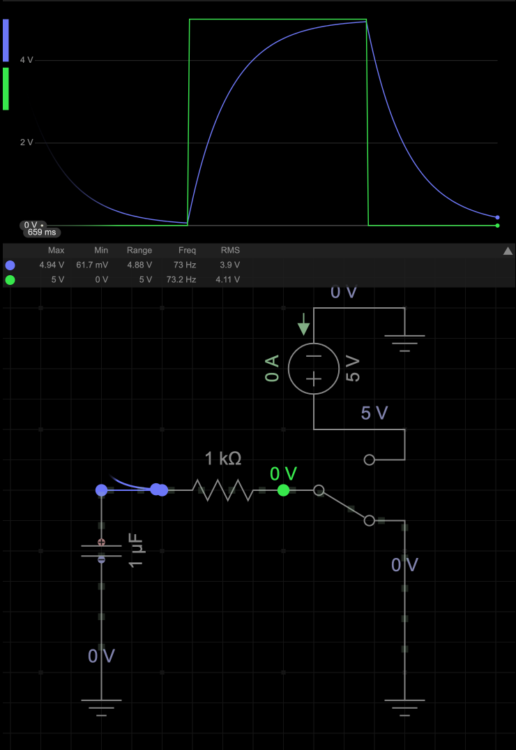
Eventually I’ll figure out how to embed the simulation directly, but that is not working right now.
Series and Parallel#
Similarly to resistors, we can find the equivalent capacitance of a circuit depending on if multiple capacitors are in series or parallel.
In parallel: \(C_{eq} = C_1 + C_2\)
In series: \(\frac{1}{C_{eq}} = \frac{1}{C_1} + \frac{1}{C_2}\)