Counters#
We just saw that when JK flip flops are put together like below they acted as a frequency divider, and that the frequency division could be interpreted as a binary number \(DCBA\). The output will count up from 0000 to 1111 before starting the cycle over again. This circuit is called a Mod-16 ripple counter.
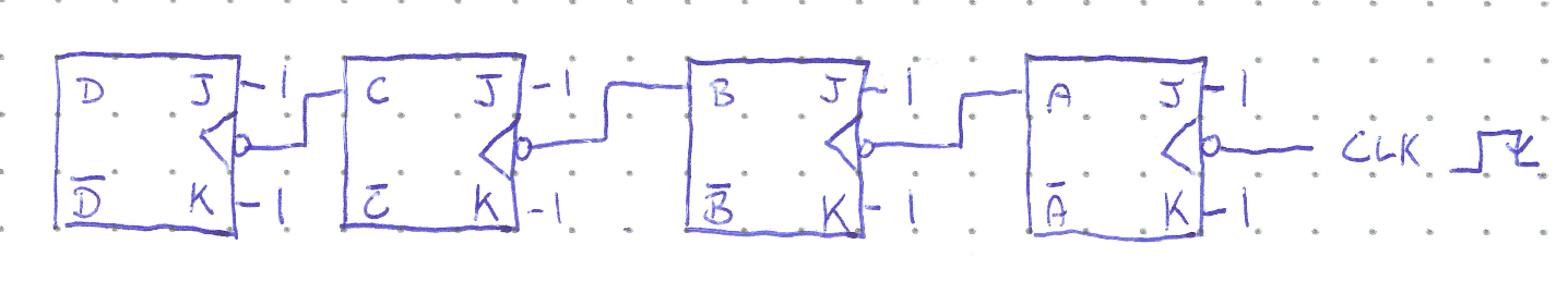
The Mod-16 refers to modulo arithmetic. Modulo can be thought of as an operation that divides a number by the modulus and returns the remainder. For example, 32 mod 16 = 0 because 32 divided by 16 is 2 with a remainder of 0. 17 mod 16 = 1, and 40 mod 16 = 8. So as regular numbers count up, those numbers mod 16 will cycle from 0 to 15 and back again once a multiple of 16 is reached. You have almost certainly used modulo arithmetic before even if you weren’t aware of it. /just think of a clock. Suppose it is 11:00 PM, what time will it be in three hours?
The mod-16 ripple counter works the same way. If \(DCBA\) starts at 0000 and the clock then goes through \(x\) cycles, this will yield an output \(DCBA = x \mathrm{mod} 16\).
The “ripple” in the counter’s name arises from how the change in each successive flip flop must propagate to the next flip flop to cause it to change, which can trigger the next flip flop, and so on. The changes spread out like ripples on a pond. A consequence of this behaviour is that the flip flops at the end of the chain toggle much later than the initial clock transition because each flip flop adds its own propagation delay to the overall time.
If there were \(N\) flip flops in a ripple counter, each with an average propagation delay \(t_{P}\), then the most significant bit will only toggle after \(Nt_P\) seconds. This limits the maximum clock frequency to be \(f_{max} = \frac{1}{Nt_P}\). Ripple counters are thus not used at high frequencies or when a large number of bits are required.
Synchronous Counters#
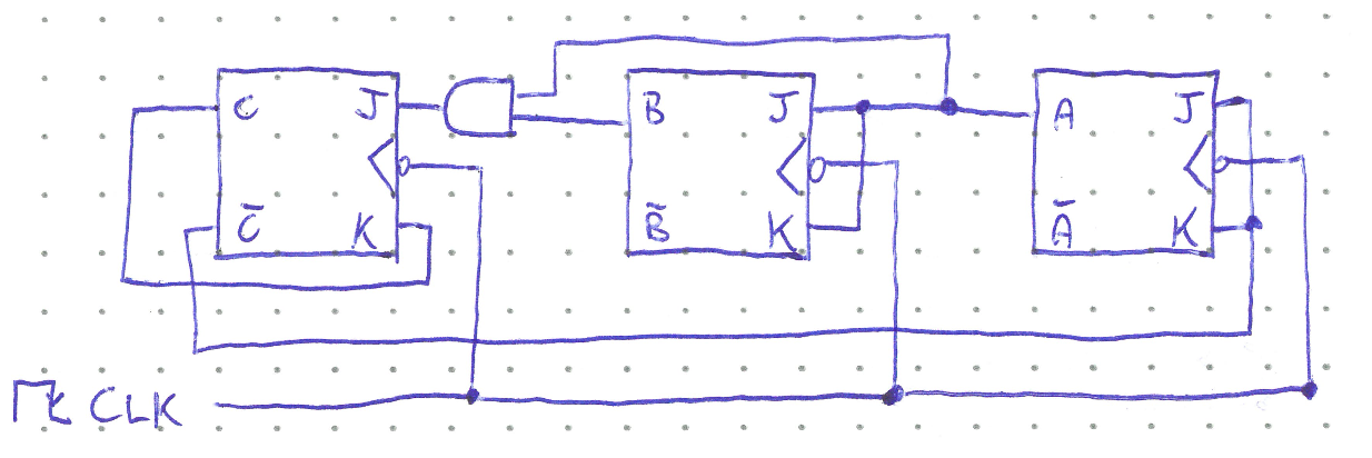
Instead of rippling through each flip flop, the clock signal can be input simultaneously into the trigger of all the flip flops, and the sequencing of transitions can be controlled by logic gates. These are called synchronous counters, and the basic Mod-16 example is shown below.
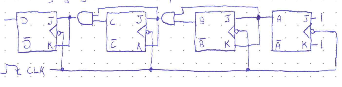
With the circuit wired like so, \(A\) will toggle with every active clock transition, \(B\) will only toggle when \(A = 1\), \(C\) will only toggle when \(AB = 1\), and \(D\) only when \(ABC = 1\). The overall output \(DCBA\) will cycle count up and cycle back just like the ripple counter, but now all the bits will change at the same time, hence the designation of synchronous. The proagation delay through a single logic gate is much smaller than that of a flip flop because no feedback is needed, so the clock can have a much larger frequency. Now the only restriction is that the period of the clock signal must be greater than the total propagation delay of one flip flop and one AND gate.
Other Moduli#
Suppose we wanted to create a counter with a different modulus than a power of two. One method is to emplot the asynchronous CLR inputs to set all the flip flops to zero once the desired modulus is reached. For example, the circuit below shows a Mod-6 synchronous counter.
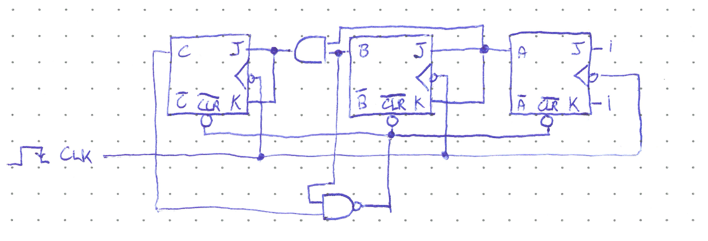
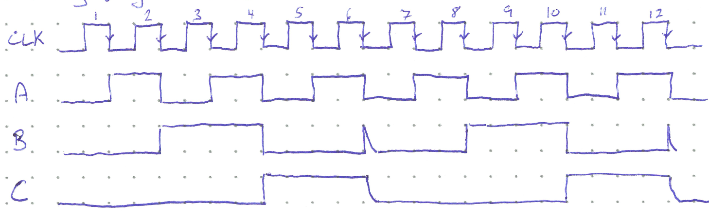
Here, once both \(B\) and \(C\) are high (which first happens at \(CBA = 110\) i.e. when the counter reaches six), the NAND gate activates the CLR inputs and resets the counter to 000. A timing diagram is shown below. Note that there will be a very brief time when the counter reads 110 before the counter is cleared. This is, in general, undesireable behavour as the counter should transition straight from 101 to 000.
A smoother transition can be accomplished by foregoing the asynchronous inputs and instead applying a more thoughtful approach to the logic gates controlling the \(J\) and \(K\) inputs. In the straightforward synchronous counter, the JK inputs are either both high and toggling the output, or both zero and having no effect. This need not be the case, and we can use logic gates to set, reset, or toggle each flip flop as needed to make the counter cycle through values in whatever manner is desired. For example, consider the counter below.
To help understand this counter, we will make a table showing all possible values the output CBA could be in, called the current state, what the JK inputs to each flip flop would be given the current state, and hence what the output would become on the next active transition of the clock.
Current \(C\) |
\(B\) |
\(A\) |
\(J_C\) |
\(K_C\) |
\(J_B\) |
\(K_B\) |
\(J_A\) |
\(K_A\) |
Next \(C\) |
\(B\) |
\(A\) |
|---|---|---|---|---|---|---|---|---|---|---|---|
0 |
0 |
0 |
0 |
0 |
0 |
0 |
1 |
1 |
0 |
0 |
1 |
0 |
0 |
1 |
0 |
0 |
1 |
1 |
1 |
1 |
0 |
1 |
0 |
0 |
1 |
0 |
0 |
0 |
0 |
0 |
1 |
1 |
0 |
1 |
1 |
0 |
1 |
1 |
1 |
0 |
1 |
1 |
1 |
1 |
1 |
0 |
0 |
1 |
0 |
0 |
0 |
1 |
0 |
0 |
0 |
0 |
0 |
0 |
0 |
1 |
0 |
1 |
0 |
1 |
1 |
1 |
0 |
0 |
0 |
1 |
1 |
1 |
1 |
0 |
0 |
1 |
0 |
0 |
0 |
0 |
0 |
1 |
0 |
1 |
1 |
1 |
1 |
1 |
1 |
1 |
0 |
0 |
0 |
0 |
1 |
To fill out the table:
First not that \(J_A = K_A = \bar{C}\). So fill in those columns with the negation of the current state \(C\).
Next, \(J_B = K_B = A\), so copy the current state A column into those columns.
\(K_C = C\)
And for the last JK input, \(J_C = AB\)
Now that we know the JK control inputs for each flip flop, we can determine what the output will transition to from any given state. For example, in the first row when the initial state is \(CBA = 000\), flip flop A is in toggle mode, while the B and C flip flops are set to not change. So the next state will be \(CBA = 001\). Repeat for every row.
Now we are finally ready to see what modulus this counter is. As stated above, if we start at \(CBA = 000\) then the next output will be 001. Looking at the row where the current state is 001, the next state will be 010. Continuing this we see \(000 \rightarrow 001 \rightarrow 010 \rightarrow 011 \rightarrow 100 \rightarrow 000...\) and the counter repeats every fifth transition. This is thus a mod-5 counter.
The states 101, 110, 111 should never be reached with this counter under ideal conditions. However errors can occur and more complex designs can be made such that any erroneous state transitions back to 000.