Timing Considerations#
Electronic circuits do not respond instantaneously to changing input; it takes time for signals to pass through components. These limitations are important to understand, especially in sequential devices like flip flops because of their feedback nature. All flip flops will have acceptable operating parameters beyond which their behaviour will not be as expected. Listed below are a few that you will be able to find on the data sheets of available ICs.
- Set Up Time (\(t_S\))
The time interval preceding an active clock transition during which the control inputs must be maintained. Typically 5 to 50 ns.
- Hold Time (\(t_h\))
The time interval after an active clock transition during which the control inputs must be held steady. Shorter than the Set Up Time. Usually 0 to 10 ns.
- Maximum Clock Frequency (\(f_{max}\))
Highest frequency square wave that can be applied to the clock input and still have the flip flop trigger reliably. Typically around 20 MHz.
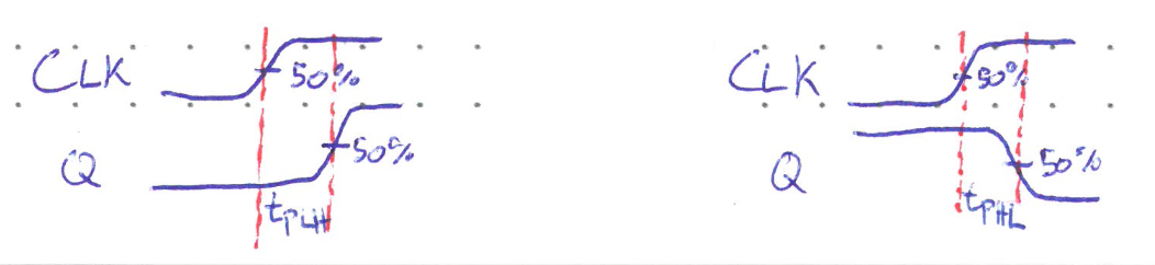
- Proagation Delays (\(t_{PLH}\) and \(t_{PHL}\))
The time from active clock transition to change in output. The propogation delay can be different for the output changing from low to high (\(t_{PLH}\)), or from high to low (\(t_{PHL}\)). Since transitions are not perfectly steep, the standard is to measure these times from 50% to 50% level.
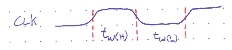
- Clock Pulse High and Low Widths (\(t_{WH}\) and \(t_{WL}\))
Minimum duration the clock signal must remain high or low. Measured from 50% to 50% level.
- Clock Rise and Fall Times (\(t_r\) and \(t_f\))
The maximum time it takes for the clock to change states, either rising from low to high (\(t_r\)), or falling from high to low (\(t_f\)). Measured from 90% of the high level to 10% (or vice-versa). Although not typically listed on the data sheet, they must be kept very short (on the order of nanoseconds). A slowly changing edge can mess up the edge detector and cause the flip flop to trigger erratically.