Logic Circuit Design#
It is important when designing logic circuits to make them as simple as possible. Doing so makes them more efficient and easier to troubleshoot. Boolean algebra can help us in this regard. However, when we are designing a logic circuit from scratch we seldom have an algebraic expression in mind. Instead, we know what we want the output to be given certain inputs. In this case the design procedure would be:
Construct a truth table showing the desired output for all input conditions.
From the truth table, write an algebraic expression in Sum of Products form. That is, wherever there is a row with a 1 in the output column, write an AND product term for the required inputs for that row. Do this for all rows with 1 in the output, then make an OR sum of all the terms. The example below should make this clear.
Simplify the algebraic expression if possible by factoring.
Draw the circuit diagram.
Example
We want to make a circuit with three inputs \(A, B, C\) and output \(X\). \(X\) should be high when only \(B\) is high, when \(B\) and \(C\) are high but \(A\) is low, and when all three inputs are high.
First we make the truth table.
A |
B |
C |
X |
|---|---|---|---|
0 |
0 |
0 |
0 |
0 |
0 |
1 |
0 |
0 |
1 |
0 |
1 |
0 |
1 |
1 |
1 |
1 |
0 |
0 |
0 |
1 |
0 |
1 |
0 |
1 |
1 |
0 |
0 |
1 |
1 |
1 |
1 |
Next we find the 1s in the output column and construct a Sum of Products expression. For example, the first term in the expression would be \(\bar{A}B\bar{C}\) because we don’t A or C to be high, but we do want B high. So, not-A AND B AND not-C.
\( X = \bar{A}B\bar{C} + \bar{A}BC + ABC \)
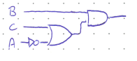
Now we see if we can simplify the expression. Notice that \(\bar{A}B\) can be factored out of the first two terms in such a way that \((\bar{C} + C)\) will simplify to 1.
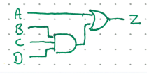
This seems to be as simple as we can make it, so now we draw the circuit.
The above example was very abstract. Try to do a more concrete example below.
Excercise:
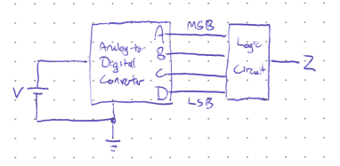
Suppose that on the international space station there is a battery that powers a life-critical system such as the oxygen circulation. It is clearly very important that the astronauts know when this battery is running low so they can change it. The voltage onthe battery is constantly monitored by an Analog-to-Digital converter, which gives the voltage level as a 4-bit binary number. The output of the converter, \(ABCD\) where \(A\) is the most-significant-bit, is fed into a logic circuit with output \(Z\) controlling a warning alarm.
Design the logic circuit so that \(Z\) is high as long as \(ABCD\) is greater than six (i.e. the battery has more than 6 Volts), and is low otherwise.
Note: the warning will trigger when \(Z\) is low, so this is an active-low circuit. Many critical systems are designed this way as a failsafe so that if the circuit stops working and stopped giving an output voltage for whatever reason the warning will sound. If the circuit was active high and broke, the warning would never sound and everyone would die once the battery lost its charge.
Solution
A |
B |
C |
D |
Z |
|---|---|---|---|---|
0 |
0 |
0 |
0 |
0 |
0 |
0 |
0 |
1 |
0 |
0 |
0 |
1 |
0 |
0 |
0 |
0 |
1 |
1 |
0 |
0 |
1 |
0 |
0 |
0 |
0 |
1 |
0 |
1 |
0 |
0 |
1 |
1 |
0 |
0 |
0 |
1 |
1 |
1 |
1 |
1 |
0 |
0 |
0 |
1 |
1 |
0 |
0 |
1 |
1 |
1 |
0 |
1 |
0 |
1 |
1 |
0 |
1 |
1 |
1 |
1 |
1 |
0 |
0 |
1 |
1 |
1 |
0 |
1 |
1 |
1 |
1 |
1 |
0 |
1 |
1 |
1 |
1 |
1 |
1 |