JK Flip Flops#
A JK flip flop is very similar to an SR flipflop, except there is no invalid input state. Instead the JK flip flop is designed such that when both inputs (now labelled \(J\) and \(K\)) are high, the output will to toggle to the opposite of its current state on an active clock transition.
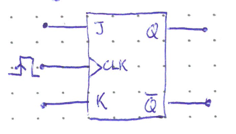
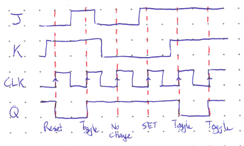
The pseudo truth table and timing diagram below show the basic functionality of a JK flip flop. The \(J\) input is the one that sets the output, and \(K\) resets it. As we shall see, the addition of the toggle functionality makes the JK flip flop much more versatile than the SR flip flop.
\(J\) |
\(K\) |
\(CLK\) |
Output |
|---|---|---|---|
0 |
0 |
\(\uparrow\) |
No Change |
0 |
1 |
\(\uparrow\) |
\(Q = 0\) |
1 |
0 |
\(\uparrow\) |
\(Q = 1\) |
1 |
1 |
\(\uparrow\) |
Toggle |
The inner circuitry is very similar to an SR flip flop, with the addition of two connections feeding the output and inverted outputs back into the pulse steering circuit.
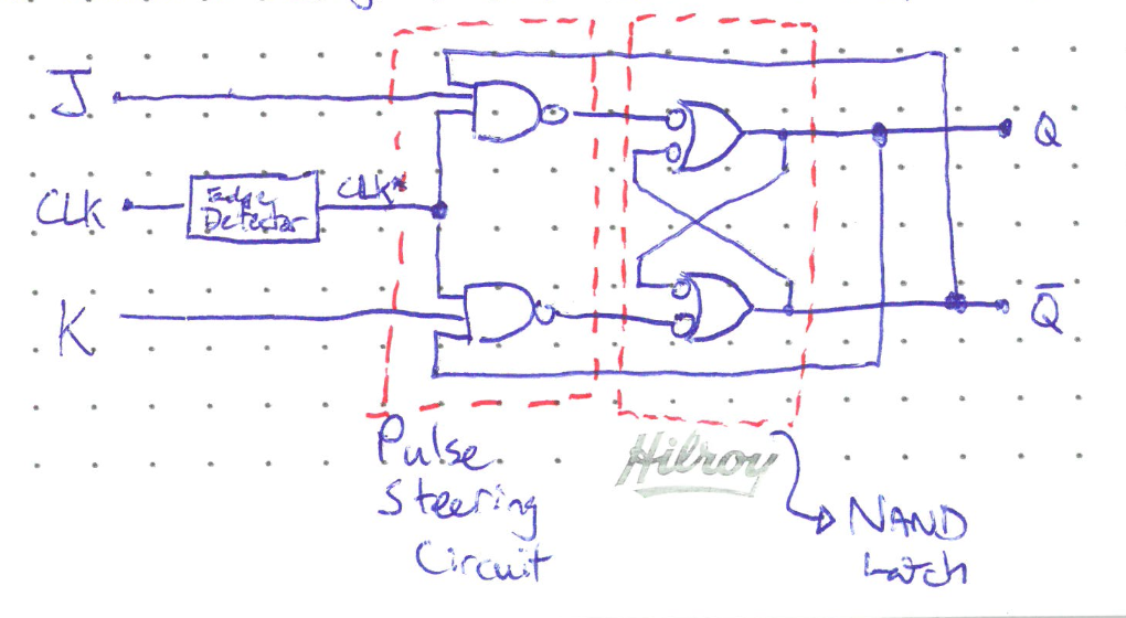
Let’s walk through an example of the toggle operation assuming \(Q = 0\) initially. To put the flip flop in toggle mode, \(J\) and \(K\) are held high and the next active clock transition will flip the output. To see how this happens, remember that NAND gates will only output a low signal when all the inputs are high. Just before the active clock transition, \(Q = 0\) and \(\bar{Q} = 1\). This means the top NAND gate will output a low signal once the edge detector output also becomes high. This low signal activates the Set functionality of the latch and changes \(Q\) to 1. This value is fed back into the bottom NAND, meaning that if we are still in toggle mode on the next active transition it will be the bottom NAND of the steering circuit that spits out a low signal and Resets the latch back to \(Q = 0\). The toggling can continue on every active clock transition as long as \(J = K = 1\).
In order for the toggle operation to work, \(CLK^*\) must be very narrow. It must return to zero before the \(Q\) and \(\bar{Q}\) outputs have a chance to change to their new values. Otherwise, the new values would change the steering circuit path and cause the same \(CLK^*\) pulse to toggle the output again.
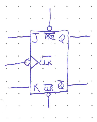
Asynchonrous Inputs#
Often it is useful to have a way to set or reset a flip flop at an arbitrary time, not just on an active clock transition. Thus flip flops commonly have two additional inputs called Preset (\(PRE\)) and Clear (\(CLR\)). These can bypass the steering circuit and set or clear the latch at any time, independent of the clock signal. The ability to do this is particularly useful on start-up since the initial state of a flip flop is essentially random on power up. An example of a JK flip flop with active low PRE and CLR inputs is shown below.