Implications of DeMorgan’s Theorems#
Universal Gates#
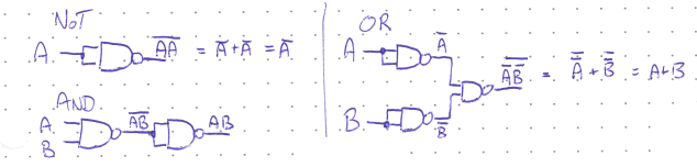
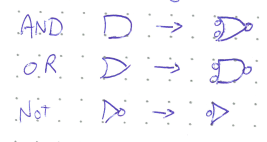
DeMorgan’s theorems lead to the interesting fact that you can construct any of the three fundamental Boolean operations using only NAND gates, or alternatively only NOR gates. These gates are thus often called universal gates. The figure below shows how to construct NOT, AND, and OR from exclusively NAND gates.
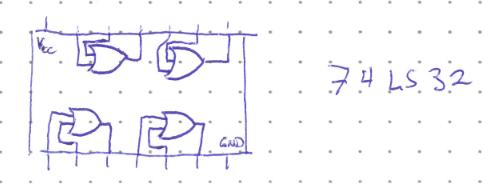
These universal gates can make circuit design more effecient in terms of cost, power consumption, and cost. Logic gates are manufactured onto integrated circuits, which typically have four of the same gate (called a quad chip). For example, the 74LS32 has four 2-input OR gates. There are 14 pins (8 inputs, 4 outputs, and Vcc and Ground for power).
A logic circuit that uses only one type of gate can usually be made smaller with fewer ICs and thus use less power. It is also cheaper to buy a single type of IC in bulk, thus saving money.
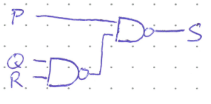
Consider the following circuit:
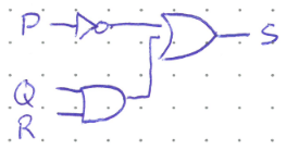
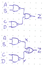
If we were to implement this as is in hardware we would have to purchase and connect three different ICs (one for the NOT gate, one for the AND, and one for the OR). But what if we were to replace each gate with its NAND equivalent?
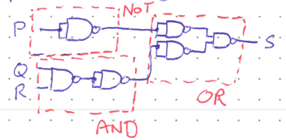
This may not look simpler, but even in this state only two quad-NAND ICs are needed. Things can be improved more, however. Notice that there are two places where the equivalent of two NOT gates appear directly in series. Two negations in a row eliminate eachother and can be removed from the diagram as they are redundant. The resultant simplified circuit uses only one quad-NAND IC.
Alternate Symbols#
Additionally, DeMorgan’s theorems mean that each logic gate can be represented by an alternate symbol using “bubbles” to represent negation.
The alternate symbols can be useful for reading logic circuits and understanding when the output is active. Active just means the circuit is doing its thing. Maybe a light is on, or an alarm is sounding. A circuit can either be active-high—it does the thing when the output is high—or active-low. It is most intuitive to make a logic circuit active high, but there are situations where active-low is better. For example, consider the concept of being fail-safe, meaning that if the circuit fails for some reason you want the default setting to be the safest one. Windshield wipers in a car are designed to turn on if there is an error in the control circuit (say from a crash), because driving with wipers in no rain is safer than driving without wipers in a rainstorm. The windshield wiper circuit would thus be active-low so that if the output is cut for some reason, the wipers turn on by default.
When an output is active-low, we use the alternate ymbols to make sure there is a bubble at the output. When the output is active high, there should be no bubble. This can often make it easier to tell what the inputs and various stages of the circuit must be to put the circuit in the active state. Any part of the circuit that needs to be low will be bracketed by bubbles, and high parts the opposite.
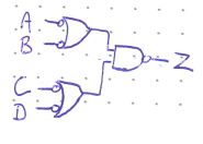
Consider the circuit below and suppose that Z is active-high. We can re-write it using the alternate NAND symbol to show that Z is active-high. Reading from the output back to the input, we can quickly see that one of the intermediary stages X OR Y must be low for Z to be active (bracketed by bubbles). And, for X to be active, both A and B must be high (no bubbles), and similarly for Y. Therefore, Z will be active when either A=B=1 or C=D=1.
Concept Check:
How would you draw the same circuit if Z was active-low?
Solution
If Z were active-low, we would keep the original NAND gate at the output because the bubble signifies active-low. We go through making sure each intermediary stage is bracketed by either bubbles at both ends or no-bubbles. This means the NAND gates at the inputs are rewritten with their alternate symbols. The circuit is thus active when either A or B are low AND either C or D are low.