Reading Simple Logic Circuits#
The pictoral representations of the Boolean operations are useful when implementing logic circuits. In physical circuits, the Boolean values are High and Low signifying the voltage levels. It is an important skill to be able to quickly convert a circuit diagram to an algebraic expression and vice versa.
Circuit diagrams are read starting from the input and moving toward the output. The gates can be oriented in whatever direction is convenient for making the diagram easy to follow, but there will always be a flow from input to output, possibly feeding into the input of another gate (or even back to the original input…we’ll save that for later). Two outputs cannot meet along the same wire (otherwise there could be a possible short circuit).
Example
Convert the following logic circuit into an algebraic expression, with intermediate expressions filled in.
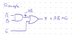
Starting from the input side, we first determine the out put of the AND gate (\(AB\)), which then becomes an input into an OR gate. The final expression is thus \(AB + C\).
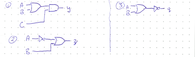
Concept Check:
For the following three logic circuits, determine the algebraic expresion of the output.
Solution
Note: If you are not seeing negation bars when you think you should, try zooming in. This is a known bug in MathJax and some browsers that will hopefully be fixed soon, but is out of my control.