NAND Latch#
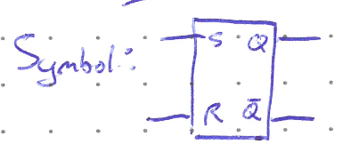
A NAND latch has two inputs called Set and Reset and labelled \(\bar{S}\) and \(\bar{R}\) respectively. The negation bars over an input is convential for active-low inputs. Please don’t get confused and think the input is automatically inverted. It just means the inputs are held high in their resting state and only change the output of the latch when pulsed low.
The NAND latch is made of two NAND gates wired together as shown below. In the image, we will consider an initial state where \(Q = 0\) and both the \(\bar{S}\) and \(\bar{R}\) inputs are in their rest state (i.e. high).
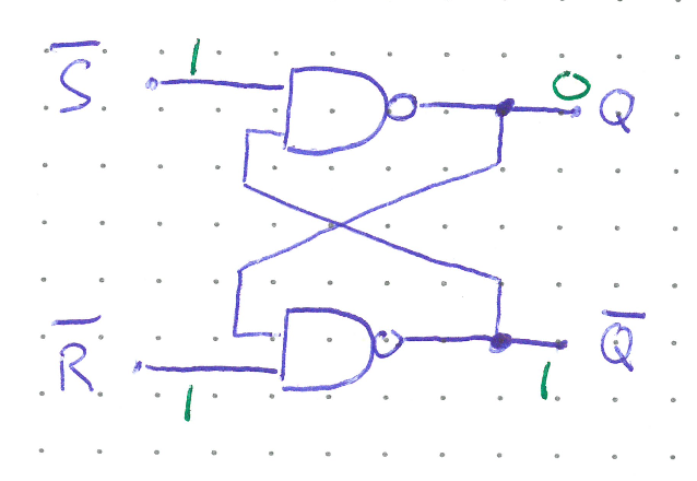
In this condition, both inputs to the top NAND are 1, and thus \(Q\) remains 0 (recall a NAND will output 0 only when both inputs are 1). Similarly, the 0 from \(Q\) being fed into the bottom NAND gate ensures the inverted output is kept at 1. The system is stable. But what happens if \(\bar{S}\) is pulsed low?
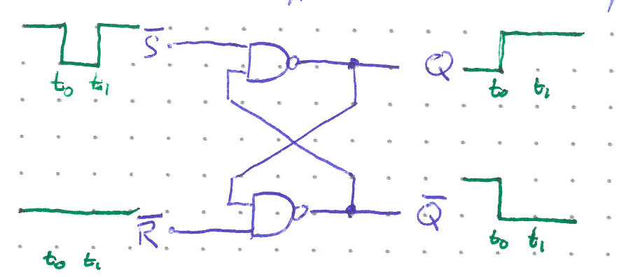
As stated above, before the pulse at \(t_0\) the regular output is low because both the Set input and inverted output are high.
Between \(t_0\) and \(t_1\) though, \(\bar{S}\) switches to low and this makes \(Q\) become high.
The high \(Q\) signal is fed back into the lower NAND gate, which switches \(\bar{Q}\) to low.
\(\bar{Q}\) being low keeps \(Q\) high. Even when the Set input returns to high after \(t_1\), or if it is pulsed low again, \(Q\) will not be affected.
Now that the latch is in the Set state (\(Q = 1\)), only pulsing the \(\bar{R}\) input low will cause the output to change back to the Reset state following a similar chain of events as above. Another way of describing this behaviour is that the latch remembers the last input that was activated. The user can essentially set and forget; they don’t need to keep holding down an input to maintain an output, simply pulse the approriate input once. The latch remembers for us and will not change states until the opposite input is activated.
Below is a pseudo truth table reflecting the behaviour of the NAND latch.
\(\bar{S}\) |
\(\bar{R}\) |
Output |
|---|---|---|
0 |
0 |
Invalid |
0 |
1 |
\(Q = 1\) |
1 |
0 |
\(Q = 0\) |
1 |
1 |
No Change |
Notice that if both inputs are low at the same time the results are unpredictable. The final state depends on which input lifts first, which could come down to slight manufacturing variances.
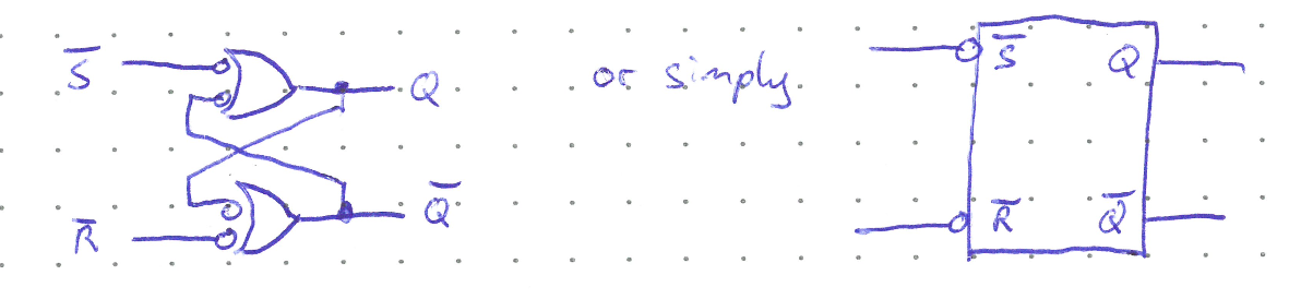
Because the inputs are active low, the NAND latch can be drawn using the alternate symbols, but is most commonly shown as just a box with not bubbles on the inputs showing they are active low.
Timing Diagrams#
Timing diagrams are very useful for determing the output of sequential devices such as the NAND latch. The diagram below shows how the output \(Q\) will change given the states of the inputs as a function of time.
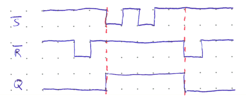
The first Reset pulse does nothing since the output is already low. Only when the Set input goes low does the output become high. It then remains that way until Reset is pulsed low again.
Note that the initial state of the latch must be known to use the timing diagram. However, many ICs will essentially have random output on power up that depend on manufacturing variances and the circuit they are placed in. To ensure a latch starts in a known state, an RC circuit can be attached to one of the inputs to guarantee it stays low longer than the other input.
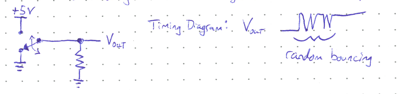
Example Usage: Eliminating Contact Bounce#
When a switch is flipped, it is not a smooth transition from ON to OFF. There will be several very short, unwanted transitions before the switch settles—known as contact bounce. The quick successions of random bounces can affect functionality or be harmful to equipment (imagine your computer turning on and then off several times a second). Consider the following switch as it changes from the bottom to top connections.
We can use the memory properties of a latch to correct the bouncing.
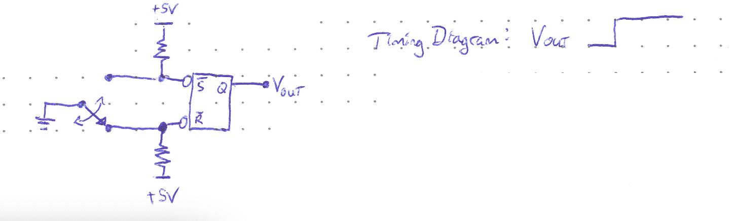
Because the Reset input is never pulsed low, even as the switch bounces against the top terminal, the output has only one smooth transition.
NOR Latch#
You can also build a latch using NOR gates and the same wiring. The NOR latch is active high, and thus will not have any not-bubbles on its diagram symbol.