Boolean Logic Gates#
In digital systems, we work exclusively with 0s and 1s and that these do not necessarily represent numbers, but rather states. For example, HI or LO, open or closed, True or False.
Often in digital circuits, there are a lot of states we need to keep track of. We want to design circuits that give certain output states for various combinations of input states. For example, we may want a warning bell to ring if the keys are left in the ignition of a car after the engine is trurned off and the driver side door is opened. As the number of inouts and outputs grows, circuits can become quite complicated, and we need to tools to helps us simplify and understand the circuits.
The most important tool at our disposal is Boolean Algebra, a mathematical system devised for working with only two states (0 and 1), referred to as logic values. In Boolean Algebra, there are no fractions, decimals, negative numbers, square roots, etc. Instead, there are just three operations: OR, AND, and NOT. Each of these operations is described below by a truth table, and each has a pictoral logic gate which is used in circuit diagrams.
OR#
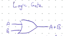
The OR operation is shown as a plus sign (+), and its operation has many similarities with regular addition. The OR of two Boolean variables \(A + B\) is True whenever at least one of the variables is True. This functionalitiy is shown in the truth table below. For example, the oven light turns on when either the oven door is open, OR the switch is turned on (the light is also on if both conditions are true).
\(A\) |
\(B\) |
\(A + B\) |
|---|---|---|
0 |
0 |
0 |
0 |
1 |
1 |
1 |
0 |
1 |
1 |
1 |
1 |
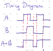
Often, timing diagrams are used to show the output of a circuit given the input. In these diagrams, time implicitly flows from left to right tracking the states of the various input and outputs.
In the timing diagram below, notice the one isolated spike in the output \(A + B\) when both \(A\) and \(B\) change states at the same time. This is called a glitch, and is an indeterminate state where the outcome will depend on the very small manufacturing differences in components that determine which input actually changed state slightly first. These should be avoided where possible.
The OR operation can have more than two inputs. In this case the out put of an OR operation will be HI as long as any one of the inputs is HI.
AND#
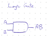
The AND operation is written similarly to multiplication, e.g. \(AB\). Its result is True only if both \(A\) and \(B\) are True. For example, you would design the heating element in a simple dryer to be on only when the dorr is closed and the timer is above zero. If either of those conditions were False, the heater should turn off.
\(A\) |
\(B\) |
\(AB\) |
|---|---|---|
0 |
0 |
0 |
0 |
1 |
0 |
1 |
0 |
0 |
1 |
1 |
1 |
The timing diagram for an AND operation might look like below.
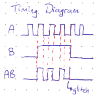
The AND operation can also have more than two inputs. It will output HI only when all the inputs are HI.
NOT#
The NOT operation takes only one input and returns the logical opposite. It is represented by a bar above the variable. For example, if \(A\) were True, then \(\bar{A}\) would be False.
\(A\) |
\(\bar{A}\) |
|---|---|
0 |
1 |
1 |
0 |
Order of Operations#
Just as the algebra you’re used to has a proper order of operations (sometimes known as BEDMAS or PEMDAS), Boolean Algebra also has an order of operations. When writing and solving Boolean expressions, the conventional order of operations is:
NOT operations
Brackets
AND operations
OR operations.
Concept Check:
Suppose \(A\) and \(B\) are True, while \(C\) is False. What would be the result of the following expression?
Solution
The answer is True.
The easiest way to approach this is to replace all True terms with a 1, False terms with a 0, and then follow the order of operations treating addition and multiplication as you normally would. I’ve used dots to indicate the AND operation for clarity, although they aren’t strictly necessary since there is no “eleven” or “ten” etc. in Boolean algebra.