Encoders#
Encoders take a large set of inputs, usually where only one is active at a time, and encode which output was active into a multi-bit output. For example, there might be eight different inputs, and the encoder will output a 3-bit binary number \(ABC\) stating which input was the active one. The encoding is very useful for something like a keyboard. Instead of having a separate wire for each key going from the keyboard to the computer, a keypress can be encoded into, say, an 8-bit binary number. This can be transmited to the computer with much less wiring.
Below is an “8 to 3” encoder. The inputs are active-low, and only one input can be active at a time for the encoder to work correctly (known as a simple encoder). The zeroth input is not connected because the default output is 000.
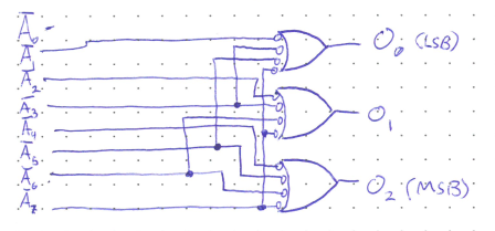
The logic of this encoder works through the principle of the NAND gate, which if you recall is Low only is all the inputs are High. This lets the zeroth input be not connected since the default output is 000 when none of the inputs are active (and thus all High). Notice that \(A_7\) is connected to all three NAND gates. Thus, if it were to be activated and turn Low, all three NAND gates would output High, or 111 which is seven in binary. Similarly, \(A_6\) is connected to the two MSB NANDs, but not the LSB NAND. If it were to become Low, the output would change to 110 (or six). All the other inputs behave in a respective manner.
If two inputs were somehow active at the same time, the circuit would not function well. For example, if both \(A_1\) and \(A_2\) were active, the output would be 011. There is another type of encoder called a priority encoder which ensures that the output will correspond to whichever active input is highest.